| Front and Rear Panel |

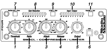
1. THRESHOLD: The setting of this control tells the compressor when to start doing its job (a reference level expressed in decibels). When the incoming signal gets above this level compression is applied. When the signal is below this level it passes through unaffected.
2. RATIO: This control determines how much compression will be applied to the signal after it crosses over the threshold. A ratio of 4:1 means that if the signal at the input increases by 4dB, the compressor will only let the output increase by 1dB. Limiting is performed when you have a high ratio (20:1) and the signal is almost not allowed to increase at all after crossing over the threshold.
3. ATTACK TIME: This controls how quickly, after the signal crosses the threshold, the full level of compression takes place. (Refer back to the figure on page 5.) There may be situations where a sound may have a sharp initial transient (slap bass), which you may not want to compress, but the rest of the signal needs to be more steady. You can increase the attack time to to allow that initial transient through, then have it kick in on the trailing part of the signal. On the other hand, if you have drums or percussion that you are limiting, you may want the attack time as fast as possible to grab a quick hold on the fast peaks that are coming in.
4. RELEASE TIME: This controls the amount of time it takes the compressor, after the signal drops below the threshold, to return to a state where it is no longer changing the signal. (Refer back to the figure on page 5.) This can be a very critical adjustment. Too short a release time can cause the signal to sound "pumpy" while too long a setting may not allow the compressor to recover in time to handle the next transient. A good rule of thumb is to set the release time so that it mimics the decay characteristics of the signal you are compressing. Use your ears to determine when you have it right.
5.OUTPUT LEVEL: After a signal has crossed the threshold the compressor begins to gradually turn down the volume in order to reduce it at a certain rate. Now that it has done this, your signal is going to be too low in level. This is where you need to adjust the OUTPUT LEVEL control.
6. ACTIVE SWITCH: Once you have all of the other controls where you want them you can use the ACTIVE switch to listen to the signal with and without compression and adjust the OUTPUT LEVEL control until the overall volume of the compressed and uncompressed signals sounds the same.
7. DUAL MONO/STEREO SWITCH: This switch allows you to use the compressor as two separate mono compressors (with a common set of controls) or as one stereo compressor. The difference is that when using a compressor to process stereo sources the two channels need to be "linked" together so that if, for example, the left channel says to compress, the compression will be applied to both left and right channels equally. If this "linking" was not done (as if you used two separate mono compressors) the compression on either channel would be different and would cause the stereo image to be disturbed. Most small compressors are stereo only, therefore you can only use one side at a time for mono. The SM4-CL allows you to use both sides, however not totally independently due to the fact that you only have one set of controls. With this in mind, the two mono sources must be similar in nature, ie: two drum toms, two vocals, two guitars...
8. GAIN REDUCTION METER: This meter indicates how much the compressor is reducing the signal level at any given time and is therefore a visual indication of the compressor doing its job.
9. LEFT/RIGHT SWITCH: Allows you to monitor both the signal level and gain reduction for both the left and right channels.
10. LEVEL METER: This meter indicates the level of signal at either the left or right, input or output depending on the setting of the associated switches.
11. OUTPUT/INPUT SWITCH: Determines whether the Level Meter is monitoring the signal at the unit’s input or output.

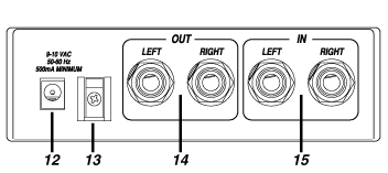
12. POWER SUPPLY JACK: Plug the smallmetal barrel connector of the AC power
adapter here.
13. CORD CINCH: Use this clip to secure the cable of the power pack to the chassis of the SM4-CL.
14. OUTPUT JACKS: These balanced 1/4" jacks* carry the output signal from the SM4-CL to its destination.
15. INPUT JACKS: These balanced 1/4" jacks* receive the input signal from the source into the SM4-CL.